Sunday 23 April 2017

The moment of truth


A pre-charge circuit was needed before the controller could safely be connected to the high voltage battery, so I followed the recommended circuit to make up the box below.


Making the final connections on a 320V battery is always a bit nerve-wracking but nothing bad happened. A final check of the control signals using the laptop, and it was time to go for the traditional first very careful trundle around the yard.


It works! Not exactly silent due to the drum brakes being full of rust (and possibly crunched up bits of brake) but that's a minor detail.

Other minor details needed before I can drive it on the road would be:
  • Trick the power steering and ABS into thinking the petrol engine is still there, so that they actually work.
  • Fit a DC-DC converter to make 12V, instead of relying on a battery temporarily thrown in the boot.
  • Fit the main battery charger. I have on the shelf a Manzanita Micros PFC-20B. This is a light weight, air cooled green box that makes nearly 5kW. I have a very early model and it hasn't been the most reliable charger ever, but at least I have been able to repair it myself on the few occasions it's needed it (Rich is generous with the tech support).


Tuesday 11 April 2017

Hit the gas

The project is getting to the stage where the motor and batteries are in, the high voltage wiring is done and it's quite tempting to just bodge enough of the other bits that make it go, as quickly as possible to be able to drive around.
The other extreme would be to get endlessly bogged down in smaller and smaller details, and never actually get it finished.

Modern cars are now nearly all "fly by wire" which means there's a potentiometer mounted right on the throttle pedal bracket, which gives an electrical signal as you press the pedal. That in turn makes a servo open the throttle valve under computer control.
So effectively they've caught up with electric vehicles which have used an electrical signal for decades.
Anyway, your older petrol cars (which the Insight definitely is) use a mechanical cable instead.
So then your EV conversion needs some sort of mechanical contraption to translate the cable pull action into an amount of rotation of a potentiometer. And no two makes of car have the same throttle cable arrangement, so there isn't a universal bolt on bit to do this.

One approach would have been to make something up out of bits of aluminium. But since my work recently got an Ultimaker 3D printer I've been trying to think of useful uses for it. So I CADed up a throttle box, and they generously allowed me to print it out.


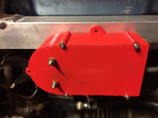
The red part is a pulley, which is hopefully (I mean carefully calculated using trigonometry) the right diameter to rotate over a suitable range of angles for the potentiometer, when the pedal is pressed. There's a place to mount the return spring and the potentiometer faces the pulley and is rotated without any side load being exerted on the shaft.

Well, we only had red PPA plastic (which is fine, it's not going to get very hot under the bonnet of an EV) and this is how it turned out:


There you can see the throttle cable at the bottom, the potentiometer resting in place, and the return  spring (ahem) at the top. The pot is from my PSA bits box, but it's a proper Potter and Brumfield part normally used on electric trains so I feel quite confident about it.


The potentiometer bolts on to the inside of the lid and the lid is screwed on. It all fits, and works!  Now I just need to find a proper spring,


Sunday 19 March 2017

Alive!

Yes, it all went quiet, but there has been some progress;

1) The motor shaft adaptor got made. The motor cartridge has an internal spline but I didn't have a matching driveshaft and getting a one off spline cut is close to impossible in this country. Instead I had a castellated piece made and ground the end of the motor sprocket to match. This is attached to a tube which passes through the motor and engages with the gearbox input shaft. To get the spline for that I had to buy a clutch on ebay and extract the centre out of it, which was then turned down and welded into the tube.  All a bit agricultural, but it feels OK so fingers crossed it will take the torque and not cause too much vibration.


2) The motor then needed its electrical connections making - this wasn't straightforward either! The stator terminals are recessed so I machined some solid copper spacers to bring them out clear of the casting so that cable lugs could be bolted down.


3) Then finally on to the wiring.  Actually no, before that, I made a bit of aluminium framework to support the inverter and contactor. This allowed all the wiring to be done with it out on the floor, and then lifted up into the space where the radiator and fan was, where it picks up the original vibration damped mounting points.


The contactor is a temporary one, the voltage I'll be using really calls for a gas filled Kilovac or similar, but I had a big two pole Sagem contactor (rated for about half the voltage).  Good enough for now with the contacts wired in series.
The RMS inverter is a lovely bit of kit, the manual and utility is excellent and apart from one small wiring error on the resolver connections it all checked out and I was able to do the calibrations and setup.


Since it was in and wired up, I couldn't resist trying it. For a quick test I ran the inverter off mains power - just a bit of two core flex plugged into a socket with a bridge rectifier attached gives 360VDC. With some trepidation I donned the safety goggles and clicked the switch to forward. As soon as I touched the throttle the lights dimmed, the motor whirred and the jacked up tyre span. Forwards! Amazing.

Now to put the batteries in and make it work properly...


Sunday 24 July 2016

On rails


I found a whole evening to spend on this project, and used it and most of a bottle or Argon to weld up the front battery support rail. Aluminium welding skills are slowly improving but it's not exactly beautiful, so no close ups! 

And here it is installed in the car, ready for the battery boxes to be bolted in.


Sunday 19 June 2016

A long wait

Too long a wait, but I finally got back into the metal workshop today and made the first of two battery packs for the front of the car, and the supporting structure that will bolt on to existing bearing points in the car.


The design of these required a bit of head scratching as the packs have to be easily removable, miss all the bits that can move such as the steering linkage, and fit under the bonnet. And it's all got to be aluminium... just because.
So, instead of a battery box (there just wasn't room) the cells support themselves and are clamped between end plates which are welded to box section beams, which in turn bolt down to the support rails in the engine bay. Seems to fit OK, more pics next time!

Monday 13 July 2015

Motorin'


Motor in, more or less

The aluminium adaptor plate came back from Jetcutit in Glasgow, and fit perfectly onto the dowels. Phew! The tooth pattern to accept the motor required the slightest bit of fettling but soon went snugly together.


The next step was to reattach the assembly to the car.  
A suitable means of supporting the motor end from the original engine mount had to be devised, and this required a bit of head scratching. In the end I used (recycled) a length of lightweight box section, as a bridge between the engine mounts, supporting the adaptor plate and the overhanging weight of the motor at the mid point. This is not the normal approach but it is straight forward, reasonably light and seems strong enough.


Thursday 4 June 2015

Abracadabra

I've got a horrible cold this week so haven't felt even slightly like doing anything, but I did have a think about how to attempt the next task on this project, that is, joining the electric motor onto the Honda gearbox.  


There you can see the gearbox bell housing, which would normally surround the clutch and flywheel.  We're not needing either, but the bell housing is cast as part of the gearbox so we have to work with it.  Simple enough - slap a metal plate across the front with suitable mounting points for the motor. The devil is in the detail of course - the first problem being how to replicate the outline to cut the plate so that it fits neatly.

I decided to try tracing the outline onto a sheet of cardboard, and use a hammer to tap through the dowels so that they are replicated precisely (like making a gasket).

Then somehow get it into the computer.


Just like magic! Or Tron, possibly.

The unusual castelated detail on the front of the motor can also be cut in to the plate, centred on the driveshaft, so that it just slots in and clamps up easily and accurately.